|
In the two-slit experiment, the common "wisdom" is that the position-momentum uncertainty relation . . . makes it impossible to determine which slit the photon (or electron) passes through without at the same time disturbing the photon (or electron) enough to destroy the interference pattern. However, it has been proven that under certain circumstances this common interpretation may not be true.
In 1982, Scully and Drühl
[2] found a way around this position-momentum uncertainty obstacle and proposed a quantum eraser to obtain which-path or particle-like information without scattering or otherwise introducing large uncontrolled phase factors to disturb the interference. To be sure the interference pattern disappears when which-path information is obtained. But it reappears when we erase (quantum erasure) the which-path information.
Since 1982, quantum eraser behavior has been reported in several experiments; however, the original scheme has not been fully demonstrated. . . .
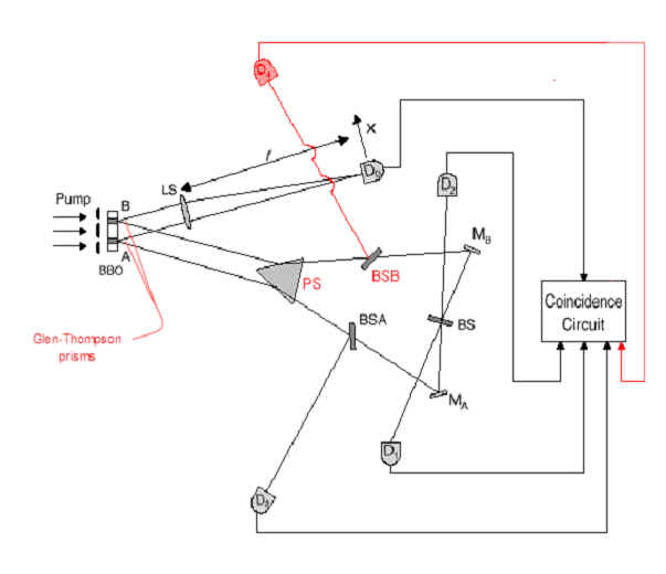
We wish to report a realization of the above quantum eraser experiment. The schematic diagram of the experimental setup is shown in
Fig. 2.
[S]pontaneous parametric down conversion (SPDC) is used to prepare the entangled two-photon state. SPDC is a spontaneous nonlinear optical process from which a pair of signal-idler photons is generated when a pump laser beam is incident onto a nonlinear optical crystal.
|
|
Comment:
In this experiment, a single photon is aimed at the double-slit. If it passes through the left slit, it will hit a crystal placed behind the slit on the left side of the crystal; if through the right slit, it will hit the crystal on the right side. We will not actually be measuring the interference vel non of the incoming photon, but of the subsequently generated photons.
When the incoming photon hits the crystal, it is destroyed and a pair of entangled photons is generated by the crystal at the spot where it hit.
Because of entanglement, the properties of the two entangled photons will forever be correlated. Therefore, if we can later identify one of the entangled photons as having come from, say, the left side of the crystal, we will thereby know,
retroactively, that its twin also came from the left side of the crystal, so that we will then know where both entangled photons came from.
On the other hand, if we cannot later identify where either of the entangled photons came from, then we will have no which-path information for either.
The remainder of the experiment consists of manipulating the pair of entangled photons. We are able to preserve which-path information for as long as we are able to identify either one of the entangled photons with respect to which side of the crystal generated it. If at any time in the course of the experiment we lose the ability to determine which side of the crystal generated the entangled pair, we thereby lose the which-path information relating to both entangled photons.
|
|
|
|
| In this experiment, the 351.1nm
Argon ion pump laser beam is divided by a double-slit and incident onto a
type-II phase matching nonlinear optical crystal BBO (b
– BaB2O4) at two regions A and B. |
 |
Comment:
The laser is able to spit out photons in a highly controlled manner. Photons from the laser are aimed at the double-slit where they are "divided," in the QM sense, between the left slit and the right slit.
(This double slit is a bit of a red herring. It is only a method of randomizing emissions from region A or region B of the crystal, which are themselves the equivalent of the two slits of Young's experiment.)
The optical crystal is placed immediately behind the slits. An incoming photon shines on the crystal ("is incident upon the crystal") at two well-defined areas of the crystal (region A and region B) because the crystal is right up next to the slits.
Note that, because of the nature of QM with its superpositions, we can
say that a single incoming photon is "incident onto a … crystal …
at two regions," despite the fact that it will "hit" the
crystal at only one or the other region. Dividing the photon via the
double slit makes its "impact" on the crystal subject to quantum
randomness. That is, it is quantumly random whether the incoming photon
will actually appear at region A or region B.
|
|
A pair of 702.2nm orthogonally polarized
signal-idler photon is generated either from A or B region. The width of
the SPDC region is about 0.3mm and the distance between the center
of A and B is about 0.7mm. A Glen-Thompson prism is used to split
the orthogonally polarized signal and idler. |
|
Comment:
When the incoming photon hits the crystal, a pair of entangled photons is generated at the point of incidence – either region A of the crystal or region B of the crystal. The two regions of the crystal, A and B, are some distance apart. (This will be approximately the distance between the two slits.) In this experiment the separation is approximately 0.7 millimeters.
The entangled pair of photons generated by the crystal (at either region A or region B) are "orthogonally polarized." That is to say, if one of the pair is polarized horizontally, the other will be polarized at right angles ("orthogonally"), i.e., vertically; and vice versa. This correlation in the respective polarizations of the pair of photons is part and parcel of their "entanglement."
The Glen-Thompson prism at the crystal is used to separate the two photons generated at the crystal. One of the pair is sent in one direction, the other in a different direction. (Here bear in mind that because of the entanglement, QM dictates that the correlation in their respective polarizations will remain regardless of spatial separation.)
Although the pair of photons generated by the crystal are identical (and correlated), the experiment will use them in different ways. Thus, one of the pair (sent in one direction) is called the "signal" photon; the other of the pair (sent in another direction) is called the "idler" photon. The designation of a particular photon as "signal" or "idler" is a matter of convention based on which direction they are sent (and how they will be used in the experiment), not any inherent difference between the two entangled photons generated at the crystal.
|
|
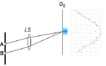
The signal photon (photon 1, either from A or B) passes a lens LS to meet detector D0, which is placed on the Fourier transform plane (focal plane for collimated light beam) of the lens. The use of lens LS is to achieve the "far field" condition, but still keep a short distance between the slit and the detector D0.
|
 |
Comment:
"Collimated" means "made parallel." The lens LS focuses photons from either of these paths onto a single detector D0.
The lens LS also allows us to control the distance (f) from the place of origin (region A or B) to the detector D0. In this way, we can fix the time it will take for the signal photon to be detected at D0.
The "far field" condition essentially makes the photons arrive at D0 as though they had traveled a long distance, even though the path is foreshortened. Like binoculars.
|
| Detector D0 can be scanned along its x-axis
by a step motor. |
|
|
Comment:
Scanning the detector along one axis provides the position information – where the signal photon actually landed on the detector D0.
At this point, we do not have which-path information. (The straight lines of Fig. 2 are diagrammatic only.) Detector D0 by itself will not be able to distinguish between a photon originating at region A, and a photon originating at region B, because nothing about this part of the experiment provides which-path information.
Without more, we would expect the pattern developing at detector D0 to be an interference pattern. QM predicts that without which-path information, photons arriving from either A or B should interfere and distribute themselves one-by-one according to the statistical distribution of interfering waves.
Mind you, if we did have which-path information, the results should be quite different. In that case, QM would predict the "clumping" pattern typical of particle motion.
|
| The idler photon (photon 2) is sent to an
interferometer with equal-path optical arms. The interferometer includes a
prism PS, two 50-50 beamsplitters BSA, BSB, two
reflecting mirrors MA, MB, and a 50-50 beamsplitter BS. |
|
|
Comment: The idler photon first encounters the prism PS, where it's path is bent to ensure it heads off where it is supposed to – one path for photons from region A, a different path for photons from region B.
The idler photon next encounters a 50-50 beamsplitter BSA or BSB. The beamsplitter will either reflect the idler photon off course and into the detector D3 or D4; or it will allow the photon to pass through and continue (toward the reflecting mirror MA or MB). QM dictates that it will go one way or the other a random 50% of the time, i.e., a 50-50 chance either way.
If the idler photon is reflected at BSA or BSB into the detector D3 or D4, it will be detected with which-path information intact. Therefore, for every photon detected at D3 or D4, we know which region of the crystal generated both it and its twin signal photon: if detected at D3, we know that both twins came from region A; if detected at D4, then both twins came from region B.
As stated earlier in the paper, "The registration of D3 or D4 provides which-path information (path A or path B) of [idler] photon 2 and in turn provides which-path information of [signal] photon 1 because of the entanglement nature of the two-photon state . . .."
If the idler photon is not reflected at BSA or BSB, it will continue toward its next encounter, the reflecting mirror MA or MB. There it will be reflected toward the single 50-50 beamsplitter BS, which is the
quantum eraser.
Here it is most interesting to note, as do the authors in the published version of the paper, that the "choice" of which direction the photon will take at BSA or BSB is made by QM itself. That is, the path at this juncture is 50-50 random. As we will see, this "choice" will determine the information available at the conclusion of the experiment. (The authors note that in other quantum eraser experiments, the choice is made by the
experimentalist. [3])
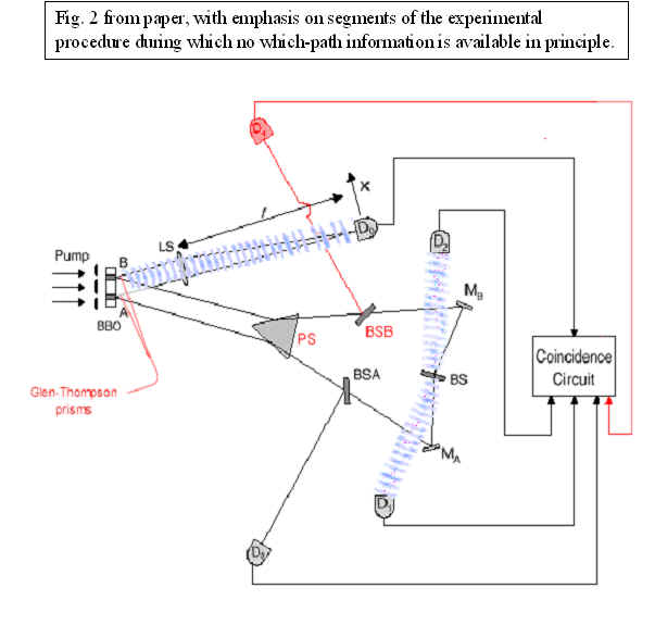
The beamsplitter BS randomizes the path information, and thereby makes the which-path information
unavailable, in the following manner.
For an idler photon coming from reflecting mirror MA, the beamsplitter BS will either reflect the idler photon into the detector D1; or it will allow the photon to pass through and continue toward the detector D2. There is a 50-50 chance either way. Similarly, for an idler photon coming from the other reflecting mirror MB, the beamsplitter BS will either reflect the idler photon into the detector D2; or it will allow the photon to pass through and continue toward the detector D1.
You can see that, with this 50-50 beam splitter, any photon arriving at detector D1 or D2 has an equal 50-50 chance of having been reflected from reflecting mirror MA or MB. It is therefore impossible to tell whether the photon was generated at region A of the crystal, or at region B. The which-path information encoded into the photons arriving at detectors D1 and D2 has been "erased."
|
|
Detectors D1 and D2 are placed at the two output ports of the BS, respectively, for erasing the which-path information.
The triggering of detectors D3 and D4 provide
which-path information of the idler (photon 2) and in turn provide
which-path information of the signal (photon 1).
|
|
Comment:
This is key. There is no which-path information for the signal photons when they initially arrive at D0. Which-path information for those signal photons is obtained only later, when the twin idler photon is later detected at D3 or D4 (and not obtained if the twin idler photon is detected at D1 or D2).
As discussed below, the experimental setup ensures that this which-path information for the signal photons is obtained or erased only after the signal photon has been detected and the information is winging its way toward the
Coincidence Circuit.
|
| The electronic output pulses
of detectors D1, D2, D3, and D4
are sent to coincidence circuits with the output pulse of detector D0,
respectively, for the counting of "joint detection" rates R01,
R02, R03, and R04. |
|
|
Comment:
Detector D0 fires once for every photon generated by the pump laser, because regardless of whether the photon hits region A or region B, a signal photon is sent to D0 for detection.
By comparing the detections of the signal photons at D0 with the other detectors, we can determine where the corresponding idler photon hit. There will be only one joint detection for each incoming photon from the pump laser.
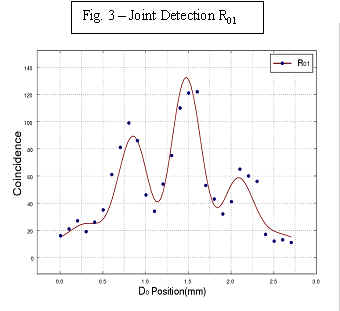
R01 records a joint detection at detector D0 and detector D1 (which-path info not available)
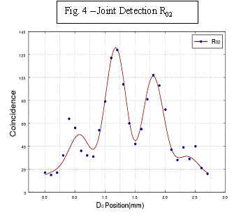
R02 records a joint detection at detector D0 and detector D2 (which-path info not available)
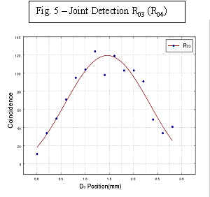
R03 records a joint detection at detector D0 and detector D3 (which-path info available)
R04 records a joint detection at detector D0 and detector D4 (which-path info available)
The joint detection event at detectors D3 or D4 (given by R03, R04) gives us new information about a photon that was previously registered at detector D0. We have already registered that photon, and the scanning has registered where it hit D0 – its position along the D0 x-axis. But when we correlate the later detection of the idler at D3 or D4, with that previous detection at D0, we now know that the photon registered at D0 came from either region A or region B of the crystal.
QM predicts that if which-path information is not available at the time of measurement, the pattern will be an interference pattern, as though wave-like photons passed through both slits and "interfered with themselves" to produce the distinctive interference pattern of hits. This is the case at detector D0 at all times.
Because which-path information is not available for photons registered at D0 even after a joint detection at the post-erasure detectors D1 and D2, we learn nothing new about the detections that have occurred at D0 and so QM predicts that R01 and R02 will exhibit this interference pattern in counting photon hits at D0.
QM also predicts that if which-path information is available at the time of measurement, the pattern will be a "clumping," as though particle-like photons passed through a slit and on to a detector in a more-or-less straight line. Because which-path information is available for photons registered at D0 once a joint detection has been indicated at the pre-erasure detectors D3 and D4, QM predicts that R03 and R04 will exhibit this "clumping" pattern.
In this experiment, "the time of measurement" is after the
correlation of the joint detections, which takes place at the
Coincidence Circuit. However, the count of photon hits that will be
displayed represents hits at D0, registered earlier.
|
|
In this experiment the optical delay (Li-L0) is chosen to be
@
[approximately equal to] 2.5m, where L0 is the optical distance between the output surface of BBO and detector D0, and Li is the optical distance between the output surface of the BBO and detectors D1, D2, D3, and D4, respectively. This means that any information one can learn from photon 2 must be at least 8ns later than what one has learned from the registration of photon 1. Compared to the 1ns response time of the detectors, 2.5m delay is good enough for a "delayed erasure".
|
|
Comment: The delay between the detection of one paired photon at D0 and the detection of its twin at D1, D2, D3 or D4 is the feature that drives home the point. At the moment when D0 registers a photon, all of the following still apply:
-
There is no which-path information about the signal photon (photon 1) detected at D0.
-
The which-path information about its twin idler photon (photon 2) is "available" because the twin is still in flight along a well-defined path coming from either region A or region B. The twin has not yet reached the first 50-50 beamsplitter BSA or BSB.
-
The which-path information about the signal photon itself is "available" in principle at D0. This is because we can correlate every photon at D0 with its twin, so that learning the which-path information about the twin (at D3 or D4) will necessarily reveal the which-path information of the signal photon at D0, albeit after-the-fact.
-
But the signal photon has already been detected, and the information about its position at D0 is already winging its way to the Coincidence Circuit, while the information about its twin idler photon is still inchoate.
-
The detecting mechanism that has tagged the which-path information (i.e., the generation of an entangled pair at either region A or region B) has already been accomplished, but it has not yet yielded up its which-path information to any observer.
However, at the subsequent moment when the twin is detected at D1, D2, D3 or D4, the which-path information may or may not be available, depending on whether the detection occurs at D1 or D2 (which-path information not available), or at D3 or D4 (which-path information available).
As stated earlier in the paper, "After the registration of photon 1 [at D0], we look at these 'delayed' detection events of D1, D2, D3, and D4 which have constant time delays . . . relative to the triggering time of D0. It is easy to see these 'joint detection' events must have resulted from the same photon pair."
|
|
Figs. 3, 4, and 5 report the experimental results, which are all consistent with prediction.
Figs. 3 and 4 show the "joint detection" rates R01 and R02 against the x coordinates of detector D0. It is clear we have observed the standard Young's double-slit interference pattern. . . .
Fig. 5 reports a typical R03 (R04), "joint detection" counting rate between D0 and "which-path" D3 (D4), against the x coordinates of detector D0. An absence of interference is clearly demonstrated. There is no significant difference between the curves of R03 and R04 except the small shift of the center.
|
|
Comment: To the physicist, the results "are all consistent with prediction." To the layperson, the results should be shocking.
Let us review the course of the experiment as it unfolds, beginning when the incoming photon from the laser generates an entangled pair at the crystal.
Time 1. The entangled pair leaves either region A or region B of the crystal. The signal photon heads off to detector D0, and the idler photon heads off to the interferometer.
Time 2. The signal photon is registered and scanned at detector D0 according to its position. This information (the position of the signal photon upon "impact" at D0) is sent on its way to the Coincidence Circuit.
Time 3. The idler photon reaches the first pair of beamsplitters, BSA, BSB. There, QM makes a choice which direction the idler photon will go – either to detectors D3, D4; or to the quantum eraser BS and on to detectors D1, D2.
Time 4a. If the idler photon is shunted to detectors D3, D4, it is detected with which-path information intact. Then and only then do we know which-path information for its twin signal photon that already has been detected, scanned, registered and recorded at D0.
Time 4b. If the idler photon passes through to detectors D1, D2, it is detected with no which-path information (the which-path information having been "erased" at BS).
Time 5. The Coincidence Circuit correlates the arrival of a signal photon at detector D0 with the arrival of its twin at D1, D2, D3, or D4. If the correlation is with an idler arriving at D3 or D4, then we know (after-the-fact) the which-path information of the signal photon that arrived earlier at D0. If the correlation is with an idler arriving at D1 or D2, then we have no which-path information for the signal photon that arrived earlier at D0.
Time 6. Upon accessing the information gathered by the Coincidence Circuit, we the observer are shocked to learn that the pattern shown by the positions registered at D0 at Time 2 depends entirely on the information gathered later at Time 4 and available to us at the conclusion of the experiment.
The position of a photon at detector D0 has been registered and scanned. Yet the actual position of the photon arriving at D0 will be at one place if we later learn more information; and the actual position will be at another place if we do not.
Ho-hum. Another experimental proof of QM. This is the way it works, folks.
Canton, Ohio
September 4, 2002
|
Phys.Rev.Lett. 84 (2000) 1-5
[additions by Ross Rhodes]
|
 |
 |
 |
|
 |
|
| Endnotes
1.
Your commentator wishes to thank Dr. Kim
for reviewing this commentary before posting.
2.
M. O. Scully and K. Drühl, Phys. Rev. A 25, 2208. "Quantum
eraser: A proposed photon correlation experiment concerning observation
and 'delayed choice' in quantum mechanics."
3.
T. Helmuth, et al., Phys. Rev. A 35, 2532 (1987); J. Baldzuhn, E.
Mohler, and W. Martienssen, Z. Phys. B 77, 347 (1989); B.J. Lawson-Daku
et al., Phys. Rev. A. 54, 5042 (1996). More recently, see V.
Jacques, et al., "Experimental realization of Wheeler's
gedankenexperiment," Science 315 966 (2007), e-print at
http://www.arxiv.org/abs/quant-ph/0610241
. |
|
|
BottomLayer.com

| Home Page | Links | Off Topic | Guestbook | Copyrights | |